3+2 CNC Milling · 304 Stainless Steel
304 Stainless Steel: Multi-Face Datum Control in a 50-Part Run
For this order of 50 parts in 304 stainless steel, OUJI combined material preparation, solution heat treatment and controlled workholding with Qiaohong (乔鸿) 3+2 indexed machining. The drawing sets 0.05 mm position requirements for holes on different faces. The published CMM excerpt shows position values of 0.0342 mm and 0.0049 mm, both below their programmed limits. The drawing, machining photographs and inspection excerpt show how the requirements were carried through the production route.

At a Glance
- Material
- 304 stainless steel
- Process
- 3+2 indexed CNC milling
- Order quantity
- 50 parts
- Machining equipment
- Chinese-built Qiaohong (乔鸿) machining center
- Heat treatment
- Solution heat treatment
- Drawing position requirements
- Ø4 H7: 0.05 mm to B → C; Ø5 H7: 0.05 mm to C → A
- Quality control
- In-process dimensional checks and final CMM inspection
- Published inspection scope
- Two displayed CMM position evaluations

From the Production Drawing
The Requirement, in the Engineer's Own Notes
The drawing specifies position 0.05 mm to B → C for the Ø4 H7 hole and position 0.05 mm to C → A for the Ø5 H7 hole. It references ISO 8015 and ISO 1101. The PDF retains the engineering information used in this case with identifying details removed. Download the redacted drawing (PDF)
01
The Challenge
The difficult part of this 50-piece 304 stainless steel order was the relationship between holes and their references on different faces. The drawing specifies a 0.05 mm position requirement for the Ø4 H7 hole relative to B → C and for the Ø5 H7 hole relative to C → A. Meeting a hole diameter alone does not establish its position. The machining plan therefore had to control how the component was located, indexed and inspected across the accessible faces.
02
OUJI's Approach
OUJI coordinated material preparation and solution heat treatment with the precision-machining route. On the Qiaohong machine, the rotary axes indexed the clamped workpiece to the required cutting orientation and held that position while the linear axes machined the features. This 3+2 CNC milling strategy reduced repeated manual reorientation for the accessible faces. Height-gauge and caliper checks supported dimensional control during machining. Final CMM evaluation then recorded position values in the programmed reference systems. Engineering reviewed and approved the change from the drawing’s B → C datum order to C → B in the program; the inspection section records that distinction alongside the results.
03
The Result
The published CMM excerpt reports position values of 0.0342 mm for FCF1 and 0.0049 mm for FCF2. Both displayed values are below the programmed limit of Ø0.0500 mm. The redacted drawing and inspection table make the requirement, datum review and measured values available together. This conclusion applies to the two displayed evaluations; 50 parts is the order quantity, not a documented inspection sample size. For a comparable part, send the drawing and datum requirements so OUJI can plan the workholding and verification route around the dimensions that matter.
Production Sequence
From 304 Stock to a Finished Multi-Face Component
The sequence follows the drawing requirements into workholding, indexed cutting, dimensional checks and final CMM evaluation. Solution heat treatment is a confirmed part of the route; the photographs document machining and inspection. The published position results follow the production sequence below.
In 3+2 indexed machining, two rotary axes orient the part and remain stationary during each cut. The three linear axes perform the machining at that fixed orientation. Maintaining a common locating arrangement across accessible faces helps control the datum relationship.

01 · Material preparation
Connect the 304 stock condition to the machining plan
The order starts with 304 stainless steel stock and includes solution heat treatment. Material condition and the thermal-processing stage must be accounted for before final dimensional acceptance. The photograph shows a rectangular workpiece in the machine fixture at the stock-setup stage.

02 · Fixturing and datums
Make the locating arrangement the reference for every face
The hole-position requirements make locating and orientation part of the machining plan. Workholding has to provide tool access and a stable reference as the workpiece changes orientation. OUJI planned the accessible faces around the locating arrangement to reduce repeated removal and re-establishment of the part.

03 · Indexed CNC machining
Cut each face from a fixed indexed orientation
The Chinese-built Qiaohong machining center positions the part for the required operation, then cuts with the rotary axes stationary. The photographed coolant-assisted machining shows the part held in its fixture while the tools reach the exposed features.

04 · Multi-face position control
Reach the next face without rebuilding the datum relationship
Indexing presents another face to the spindle while retaining the workholding reference. This is the central advantage for this component: the related bores, pockets and surfaces can be machined with less setup-transfer variation. Their position still has to be verified against the drawing.

05 · In-process height checks
Check intermediate dimensions while adjustments are still practical
Height-gauge checks provide feedback on accessible dimensions during production. They help the team assess the current machining state before continuing with the remaining operations. The photograph documents this intermediate check, without presenting it as a complete position-tolerance inspection.

06 · Shop-floor dimensional checks
Use accessible feature checks to support process control
Caliper checks complement the intermediate inspection by checking accessible feature sizes. These checks support machining decisions; final evaluation of the relationships between faces uses the drawing datum scheme and the CMM inspection route.

07 · Final CMM inspection
Bring the finished faces back into one inspection reference
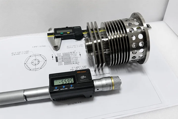
The coordinate measuring machine probes the finished component and evaluates the features in the programmed reference systems. The photograph shows the probing setup; the anonymized screenshot below supplies the two published position readings. Their programmed datum orders and limits are recorded with the values so the result can be read in context.

08 · Finished component
Review the features as one functional part
The finished geometry brings together features reached from different machining directions. For this 50-part run, OUJI’s process connects the 304 material, thermal treatment, fixture, indexed machining and inspection so dimensional control follows the component through the full route.
Inspection Results
Two Position Results, with Their Programmed Limits
The table follows the feature labels displayed in the CMM program: FCF1 (circle 1) and FCF2 (circle 2). These report labels are kept separate from the drawing’s hole callouts. Both displayed position values are below the programmed limit of Ø0.0500 mm.

Anonymized CMM screenshot excerpt showing two programmed position evaluations.
Open full-size inspection excerpt| Displayed report feature | Programmed datum order | Programmed position limit | Displayed axis deviations | Displayed position result |
|---|---|---|---|---|
| FCF1 (circle 1) | C → B | Ø0.0500 mm | Y +0.0167 mm; Z −0.0037 mm | 0.0342 mm |
| FCF2 (circle 2) | C → A | Ø0.0500 mm | X −0.0018 mm; Z −0.0017 mm | 0.0049 mm |
How to interpret these results
Engineering reviewed and approved the change from B → C on the drawing to C → B in the CMM program. The drawing references ISO 8015 and ISO 1101; the screenshot shows an ASME Y14.5 setting. The displayed values are compared with the programmed limits, without claiming that the standards or datum orders are interchangeable. The excerpt covers only the two displayed program results. It is not a complete CMM certificate or a sampling plan for the 50-part order.
Project questions
Why use 3+2 CNC machining for a multi-face 304 stainless steel part?
3+2 indexed machining reaches several faces from controlled orientations while retaining the workholding reference for the accessible features. For this 50-part case, that reduced repeated setup transfers and helped OUJI maintain the relationship between features on different faces.
Does solution heat treatment harden 304 stainless steel?
304 is an austenitic stainless steel and is not hardened by conventional quench-and-temper heat treatment. Solution treatment is used to restore a suitable metallurgical condition. This project includes solution heat treatment, but no furnace temperature, holding time or cooling parameters are published.
How does OUJI control position across multiple faces?
The process combines a consistent locating arrangement, controlled indexed orientations, in-process checks and final CMM inspection against the drawing datums. Feature size and feature position are separate checks; the true-position guide explains that distinction and how an explicitly specified MMC modifier affects evaluation.
What should I send for a similar 304 machining quotation?
Send the 3D model, dimensioned drawing, quantity, 304 material condition, heat-treatment requirements and inspection requirements. Mark the datum references and position tolerances clearly so OUJI can review the fixture, machining orientations and final verification together.
What do the published CMM results establish?
The screenshot displays position values of 0.0342 mm and 0.0049 mm against programmed limits of Ø0.0500 mm. Both displayed values are below the programmed limit. The engineering-approved datum-order change and the differing ISO drawing references and ASME program setting are stated with the results. This excerpt documents the displayed evaluations, rather than acceptance of every drawing requirement or all 50 parts.
Sources & technical references
- Post-fabrication treatment of stainless steels — Outokumpu
Technical background on solution annealing. Project facts and photographs are supplied by OUJI; this reference is not a production or inspection record for the order.
Have a project-specific question?